Bit Banging a 3.5" Floppy Drive
Welcome to the floppy cafe! These pages are the lost and sacred texts you've been looking for if you happen to be writing a driver for a 3.5" floppy. To learn these mysteries, I bit-banged a floppy drive using a teensy4.0 and managed to write a full driver for it. My project code is hosted here on github in case you'd like to learn more. Continue reading for an extremely detailed overview of the project and all my findings on this adventure. Although the information is largely common for any floppy drive, floppy.cafe is dedicated specifically to 3.5" media.
Table of Contents
 How do Floppy Disks
Work?
How do Floppy Disks
Work?
This
website
has a good overview and some nice pictures. Fundamentally, your floppy
houses a magnetized disk that spins at about 300rpm. For 3.5" media,
that disk contains 80 tracks. Each track has 18 sectors. Each sector has
512 bytes of user-space data (and some more bytes used for metadata).
Most "modern" floppies are double-sided, so you can multiply all that by
2 in order to find the total amount of usable space per disk.
1,474,560 bytes in all.
Fun fact! floppy disks actually contain a lot more surface area than 1.44mb. By my calculation, you'll get closer to 1.70mb but a lot of that extra space is earmarked for synchronization barriers and sector / track metadata.
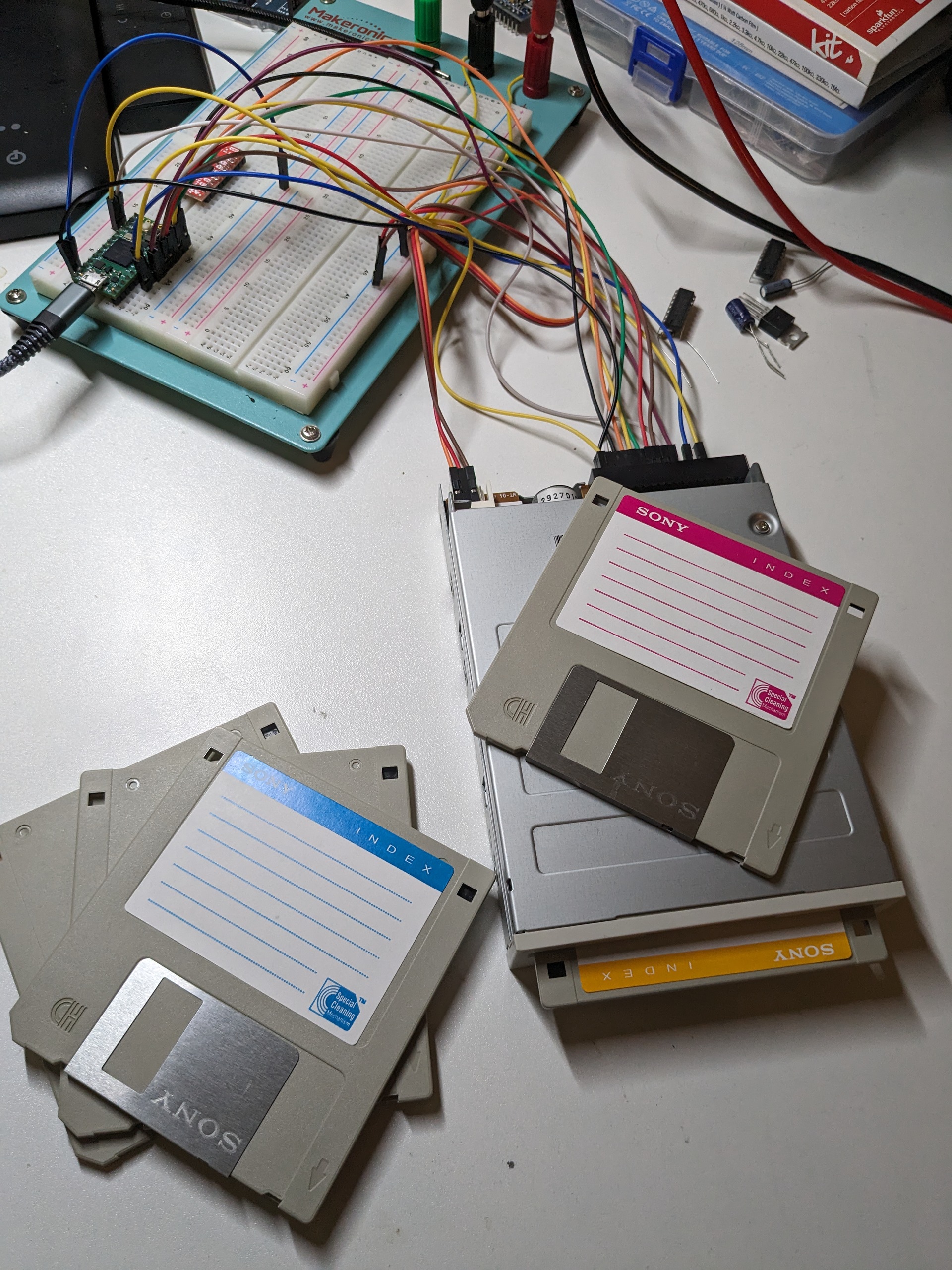
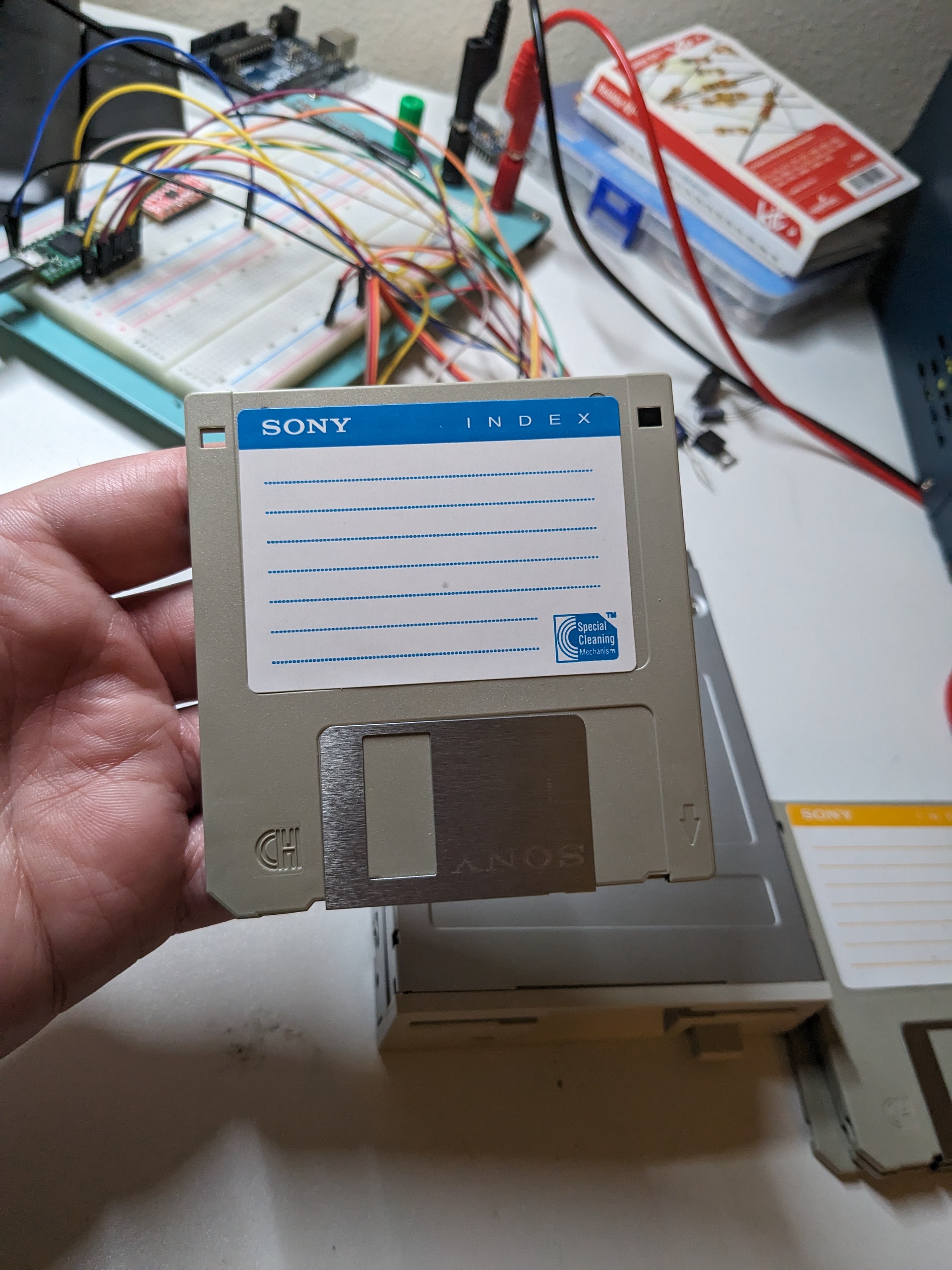
Wiring Guide
Here's the cool thing about floppy drives: they have no communication
protocol! It's just a bunch of gpio pins. For most of them, pulling the
pin HIGH means it is in the "disabled" or "off" state.
Pulling a pin LOW will activate it. You can read about the
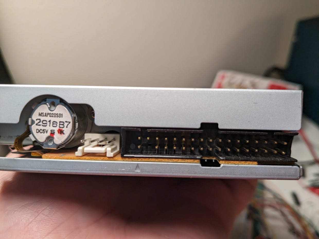
very detailed specifications for the
SAMSUNG-SFD321B
floppy drive. The top row of pins are the functions, the bottom row of
pins are all LOGIC GROUND. Logic. Did you get that? LOGIC! Not
motor ground. I had them wired up wrong for weeks and wondered why
nothing worked. And, yes, there's like a million ground pins but you
only need 1 to get it working.
An important note! the logic-level pins are rated for 5v, however, you can use 3v3 in a pinch! Why is that? All these data pins are open drain and should be hooked up to a pull-up resistor. That means the only way these floppy drives communciate back is by sinking the voltage. So 3v3, 5v, it doesn't matter. The floppy drive will happily pull it down.
Protip! Some of the bottom row of pins are not connected internally! So if you are plugging in just 1 ground wire and it's not working, chances are the ground pin you selected is disconnected. Try another one.
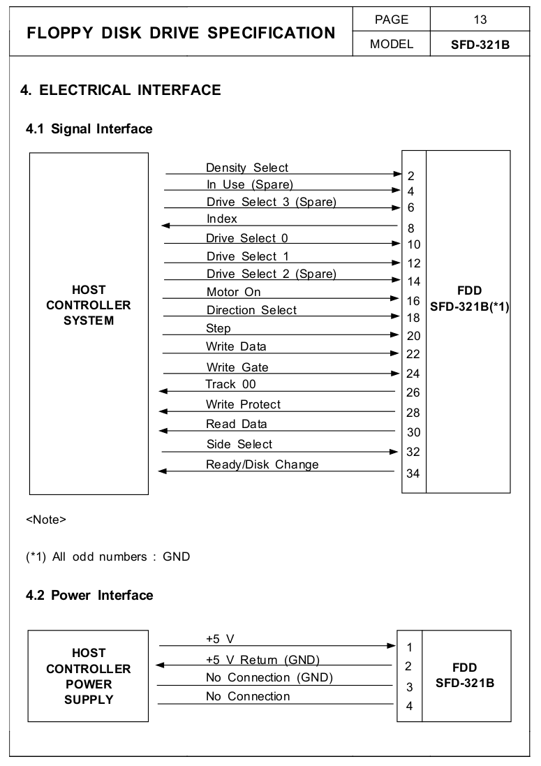
You'll notice the power section only needs two wires. 5v+ and another ground. For your sanity, I suggest using a separate power bus than whatever your microcontroller is on.
Please do not connect the 5v+ to an arduino or a GPIO! It can draw upwards of 1A during really feisty operations and it will fry your microcontroller!
Sending Commands
There are a number of commands and proceedures you will need to
implement in order to assume control of the floppy drive. In general,
commands are issued by pulling a given pin LOW.
A word of warning: I've read online the Arduino internal pull-ups
aren't great. They'll work for most of these pins
except the data line. You may want to add a 4.5k pull-up to the
DATA line instead of relying on the built-in pull-ups.
Alright! Let's explore each function you have access to.
Index
The floppy drive doesn't really know where you are at any given
time. You can suss this out with various mechanisms, and one of those
mechanisms is the INDEX pin. The index pin is the first usable
pin on the top row (pin 8). When this pin is LOW, the disk
has made one complete revolution and is currently at the start of the
data stream.
In my driver, I would often look for HIGH to
LOW transitions and use this to increment an error counter.
If I can't complete some task after 10 revolutions or so, I consider the
drive in a bad state.
Drive Select
There are a few different drive select pins (often for drive 0, 1, and
2) but the main one we're interested in is
PIN 12 also known as DRIVE SELECT 1. The other
ones are reserved for controlling multiple floppy drives at once. This
function is used to enable the floppy drive. Pulling it
LOW
will provide you access to all the other I/O functions except
MOTOR ON. That one is agnostic of drive select.
Motor On
As the name suggests, this pin is dedicated to controlling the motor. To
enable the motor, pull this pin
LOW and then wait 500ms. It's good practice to monitor the
INDEX line as well for a HIGH to
LOW transition, indicating that the spindle has made a
complete revolution.
Direction Select
This pin controls the direction that the track stepper motor pin
will move in, when you pulse the STEP pin. Pulling this pin
LOW will orient the track stepper motor to move towards the
center of the magnetic disk (increasing the track number). Pulling this
pin HIGH will orient the track stepper to move towards the
outside of the magnetic disk (decreasing the track number).
Step
There are 80 tracks on your average 3.5" floppy drive. You can select a
given track by pulsing the STEP pin and combining it with
the direction select pin.
Pulsing this pin will charge and actuate a stepper motor. As such, there
are some specific timing requirements. I like to pull it
LOW for 3ms and then pull it
HIGH for an additional 3ms and leave it in the
high state until the next pulse. The documentation states it can be low
for as short as 0.15us but that didn't work for me
consistently across other drives.
Write Data
If you want to know a lot more about this pin, head on over to the
MFM ENCODING page for a primer on how to use it.
From a technical perspective, pulsing this pin will reverse the flux
direction on the magnetized disk. In general, you will hold the pin
LOW for about 0.15us to 1.1us and then bring
it back to a HIGH state. How long it remains in the high
state determines the encoded value according to the MFM rules.
Write Gate
Pusling the write data pin will do nothing if the gate is closed. To
begin writing data, you must pull this pin LOW and keep it
low during your write operation.
You cannot read and write at the same time.
Fun fact! While I was developing my driver, I ruined many entire tracks by leaving this open for too long. If you aren't careful, it'll wreck the sector metadata and synchronization barriers and totally destroy your floppy disk. Reformatting the disk should restore balance to the force, so this won't be a total loss.
Track 00
The floppy drive controls this pin, and when it gets pulled
LOW that means the read/write head is positioned on
the first track (track 0).
Write Protect
When a write-protected media is insertted, this pin will be pulled
LOW by the floppy drive and the data on the disk is
protected from mis-erasing. When the pin is HIGH the
floppy drive can be written.
This only seems to work if the drive select pin has been pulled low.
Read Data
A HIGH to LOW transition on this line
indicates the flux direction has changed on the underlying magnetic
disk. Once you encouter this transition, count all the clock cyles
between the leading edge of the LOW signal to the
trailing edge of the HIGH signal.
Side Select
These 3.5" floppy disks have 2 sides. Pulling this pin
HIGH selects the lower side (side 0). Pulling this pin
LOW selects the upper side (side 1).
Ready/Disk Change
I never got this to work, but the spec says it will either tell you if
the drive is in a ready state or not. When the floppy drive pulls this
pin LOW, the drive is ready for operation. Otherwise, the
pin will be left in a HIGH state.
Synchronization
Barriers
Between each track is a synchronization barrier. This barrier is
surprisingly easy to find because it is just 12 0x0 bytes
followed by 3 0xA1 bytes. In terms of pulses, it amounts to
to 96 short pulses followed by the sequence of pulses MLMLMSLMLMSLMLM.
You may have trouble reading all 96 pulses because of timing. A common
practice is to seek for at least 80 pulses instead.
This will give you a bit more resilience.
Sector Metadata
Each sector is comprised of some metadata to describe it. The metadata is formatted like so:
- 12 bytes of 0x0
- 3 bytes of 0xA1
- One byte of 0xFE
- One byte to indicate the track number
- One byte to indicate the side (or head)
- One byte to indicate thes sector number
- One byte to indicate the sector size
- 2 bytes of CRC (cyclic redundancy code) computed from the sector metadata
- 22 bytes of 0x4E
- 12 bytes of 0x0
- 3 bytes of 0xA1
- 1 byte of either 0xFA or 0xFB
- 512 bytes of user data
- 2 bytes of CRC computed from the user data
- Unspecified amount of 0x4E bytes filling in the remaining space between sectors
Upon careful inspection, we can see there are actually two synchronization barriers. One to find the sector metadata, and another to find the userspace data. The only difference is the byte that follows. For sectors, the immediate byte after the barrier is 0xFE. For userspace data, it's either 0xFA or 0xFB. This is how we can determine which kind of barrier we've run into.
Track Metadata
Each track also has its own set of metadata which is formatted like so:
- 80 bytes of 0x4E
- 12 bytes of 0x00
- 3 bytes of 0xC3
- One byte of 0xFC
- 50 bytes of 0x4E
Further Reading
Here is a comprehensive list of additional resources:
- SFD321B-070103.pdf
- Floppy Disk Formats
- Floppy Drive PinOut
- MFM Reader
- (github) Floppy Driver RS
- (github) Adafruit Floppy Reader
- (github) Arduino FDC
Next, let's check out MFM ENCODING to learn more about how data is stored.